Different Types of Switches
What is a SWITCH? The switch is nothing but a device that is used to turn ON and OFF the equipment. Most probably this equipment is electrical equipment like fan, TV, etc. To flow current from a circuit it must require a close path (loop). If the switch is OFF, that means the circuit is open and current cannot flow through the conductor and equipment is de-energise (OFF state). To make it energize, we have to turn ON the switch, it makes a complete circuit and close path. So, current can flow through the equipment and it can turn ON. So, function of switch is to make (switch is ON) and break (switch is OFF) the circuit.
In control system engineering, switches play an important role. There are mainly two types of switches- mechanical switch and electrical switch. Mechanical switches require physical or manual contact with switch for operation. Electrical switches not require physical or manual contact, it has ability to perform operation. Electrical switches operate under the action of semiconductors.
Mechanical Switches:
Mechanical switches further classify into different types of switches based on number of poles and throughs. Poles means the number of input circuit (power circuit) available to the switch. Throws means the number of output circuit (number of path in which current can flow) available to the switch.
- Single pole single throw (SPST)
- Single pole double throw (SPDT)
- Double pole single throw (DPST)
- Double pole double throw (DPDT)
- Two poles six throw (2P6T)
- Momentary operation switch / Momentary control switch
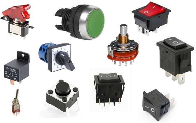
- Push button
- Pressure switch
- Temperature switch
- Toggle switch
- Rotary switch
In mechanical switch, two metal plates are touch each other to complete circuit for the current to flow and separate each other to open circuit for the current to interrupt.
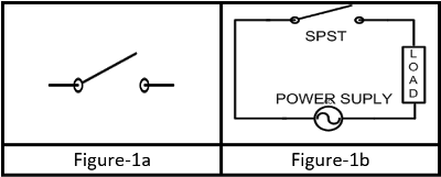
1) Single pole single throw (SPST): This switch consists of two terminals; one input terminal is known as pole and one output terminal is known as throw. So, name of this switch is single pole single throw. This switch is simplest example of switch. Generally, this switch used in single loop, means circuit requires to control only one close path. Symbol of single pole single throw switch is as shown in figure-1a. This switch is connected in series with the equipment, source or elements as shown in figure-1b.
Working and symbol of SPST
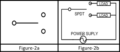
2) Single pole double throw (SPDT): This switch consists of three terminals; one input terminal (pole) and two output terminal (throw) as shown in figure-2a. By using this switch, we can supply current or signal to two loops as shown in figure-2. Sometimes this switch is known as selector switch.
Working and symbol of SPDT Type 1
Working and symbol of SPDT Type 2
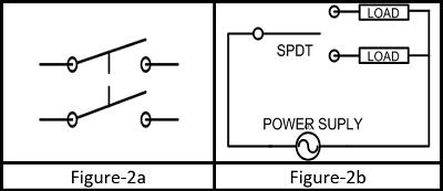
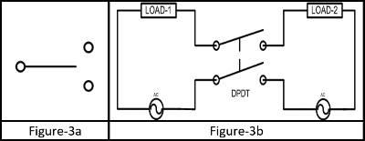
3) Double pole single throw (DPST): This switch consists of four terminals; two input terminal (pole) and two output terminal (throw) as shown in figure-3a. This switch is very similar to two SPST switches. Both switches are connected with single liver so, both switches operate at a single time. These switches used when we want to control two circuit for same time as shown in figure-3b.
Working and symbol of DPST
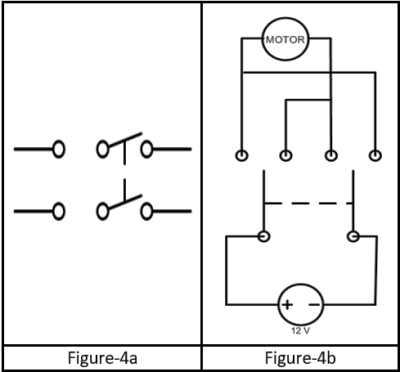
4) Double pole double throw (DPDT): This switch consists of six terminals; two input terminals (pole) and two terminals for each pole, so total four output terminal (throw) as shown in figure-4a. Operation of this switch is similar to the two separate SPDT switches operate at a same time. In this switch, two terminal of input (pole) are connected with one set (two) of output (throw-1) in position-1 of switch. If we change the position of switch, it will connect this input with second set of output (terminal-2) as shown in figure-4b. Here as shown in example, let us assume that, in position-1 if motor is rotating in clockwise direction, if we change to position-2 motor will rotate in anti-clockwise direction.
Working and symbol of DPDT
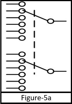
5) Two poles six throw (2P6T): This consists of fourteen terminals; two input terminals (poles) and six terminals for each pole, so total twelve output terminal (throw) as shown in figure-5a. Generally, this type of switch is used for change-over in circuit with common input terminal.
Symbol of 2P6T
6) Momentary operation switch:
- Push button switch: when you press the switch, contacts of switch is closed and make circuit close to flow the current and when you remove pressure from the button, contacts of switch is open and break the circuit. So, this switch is momentary contact switch which is able to control the circuit by making and breaking its contact. In push button switch, when you remove pressure from the switch, there is an arrangement of spring to open contact.
- Pressure switch: This type of switch consists of C-shape diaphragm. According to pressure, this diaphragm is indicating pressure. These switches are used to sense pressure of air, water or oil, in industrial application. This switch operates, when pressure of system is increase or decrease from set point.
- Temperature switch: This type of switches consists of temperature sensing devices like RTD (resistance temperature device). This switch operates according to the value of measured temperature.
- Toggle switch: This type of switch is commonly used in household application to ON and OFF electrical appliances. It has a lever by which we can move up or down to ON and OFF appliances.
- Rotary switch: This type of switch is used to connect one line with one of the many lines. Nob of multi-meter, channel selector, range selector metering device band selector in communication devices are the examples of this type of switch. This switch is same as single pole multi throw switch. But the arrangement of this switch is different.
Electrical Switches:
Electrical switches are nothing but it is a semiconductor device. These switches are more useful because of their low cost, small size and reliability. In this switch, used semiconductor materials like silicon (Si), germanium (Ge) etc. Generally, this type of switches is used in integrated circuits (ICs), electrical motor drives, HVAC application and also widely used as digital output (DI) of controller.
- Relay
- Bipolar transistor
- Power diode
- MOSFET
- IGBT
- SCR
- TRIAC
- DIAC
- GTO
1) Relay: Relay works on the principle of electromechanical, so this switch is also known as electromechanical switch. When current pass through a coil, it will create a magnetic field around the coil. This amount of magnetic field depends on the amount of current passes through the coil. Arrangement of contacts is done such a way that, if current is increased with curtain limit contacts are energised and change its position. Sometimes, relay uses bi-metallic strip to sense the temperature for safety purpose. Relay are available in wide range of voltage and current. In power system, relay plays an important role in fault identification. In industries also, relays are used as a protecting device. Check the complete Working of Relay here.
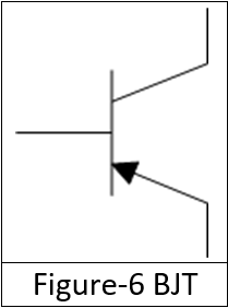
2) Bipolar Transistor: bipolar junctions transistor has three terminals; base, emitter and collector. Transistors are work on three regions; cut-off, saturation and active region. Symbol of transistor is as shown in figure-6. For switching purpose, active region is not used. If sufficient amount of current is available at base terminal, transistor enter in to saturation region and current will flow through collector-emitter path and transistor act as a ON switch. If base current is not sufficient, circuit is open and current cannot flow through the collector-emitter and transistor enters in to cut-off region. In this region, transistor act as OFF switch. Transistor are used as an amplifier in electronics application and it also used to make a gate like AND, NOT in digital circuits and transistor is also used as a switching device in integrated circuit. Transistors are not useful in high power application because it has more resistive loss compared to MOSFET.
3) Power diode: Power diode have two terminals; anode and cathode. Diode is made up of p and n type semiconductor material and make pn-junction, which is known as diode. Symbol of power diode is as shown in figure-7. When diode is in forward bias current can flow through the circuit and in reverse bias blocks current. If anode is positive with respect to cathode, diode is in forward bias and act as a switch ON. Similarly, if cathode is positive with respect to anode, diode is in reverse bias and act as a switch OFF. Power diodes are used in power electronics application like, rectifier, voltage multiplier circuit and voltage clamper circuit, etc.
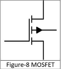
4) MOSFET: MOSFET-Metal Oxide Semiconductor Field Effect Transistor. MOSFET has three terminals; gate, drain and source. MOSFET is works on two basic forms; Depletion type and Enhancement type. If gate-source voltage (VGS) is not sufficient, MOSFET works as depletion type and depletion mode of MOSFET is similar to OFF switch. If gate-source voltage (VGS) is sufficient, MOSFET works as enhancement type and enhancement mode of MOSFTE is similar to ON switch. Range of switching of MOSFET is tens of neon seconds to a few hundred microseconds. MOSFET used in linear voltage regulator, chopper and audio frequency power amplifier, etc. Check here for MOSFET Circuits.
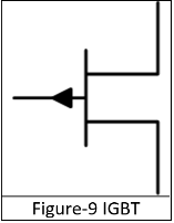
5) IGBT: IGBT- Insulated Gate Bipolar Transistor. IGBT is a combination of BJT and MOSFET. IGBT has a high input impedance and high switching speeds (characteristic of MOSFET) as well as low saturation voltage (characteristic of BJT). IGBT has three terminals; Gate, Emitter and Collector. IGBT can control with the use of gate terminal. It can be switched ON and OFF by triggering and disabling its gate terminal. IGBT can block both positive and negative voltage same as GTO. IGBT is used in inverter, traction motor control, induction heating and switched mode power supplies.
6) SCR: SCR- Silicon Controlled Rectifier. SCR has three terminals; Gate, Anode and Cathode. Working of SCR is same as diode, but SCR start conduction when it is in forward bias (cathode is negative and anode is positive) and positive clock pulse at the gate is also required. In forward bias, if clock pulse of gate is zero, SCR turned off by forced commutation and in reverse bias SCR is remains in OFF state same as diode. SCRs are used in motor control, power regulators and lamp dimming.
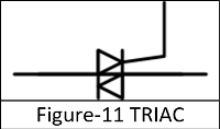
7) TRIAC: TRIAC is same as two SCRs connected in inversely parallel with gate connected. TRIAC is bi-direction device. TRIAC has three terminals; Main terminal 1 (MT), Main terminal 2 (MT2) and gate. MT1 and MT2 terminals are connected with circuit which we want to control and gate is available for triggering pulse by positive voltage or negative voltage. When MT2 terminal is at positive voltage with respect to MT1 terminal and gate is also positive triggered, then SCR-1 of TRIAC triggers. When MT1 terminal is at positive voltage with respect to MT2 terminal and gate is also positive triggered, then SCR-2 of TRIAC triggers. TRIAC can used for both sources AC and DC but generally, TRIAC is used in AC application like motor control, switching in lights (industrial and domestic), etc. Check here for Triac Dimmer Circuit.
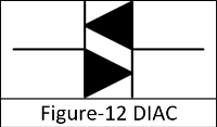
8) DIAC: DIAC- Diode AC switch. DIAC has two terminals. This switch can operate in both direction. Symbol of DIAC is as shown in figure-12. DIAC works on two regions; forward blocking or reverse blocking region and avalanche breakover region. When applied voltage is less than breakover voltage DIAC works in forward blocking or reverse blocking region. In this region DIAC act as OFF switch. When applied voltage is greater than breakover voltage, avalanche breakdown occurs and DIAC act as ON switch. DIAC cannot switch sharply for low voltage and low current application as compared to TRIAC and SCR. DIAC used in light dimming, control of universal motor and heat control circuit.
9) Gate Turn-off Thyristor: GTO has three terminals; Gate, Anode and Cathode. As name suggest, this device can turn OFF through gate terminal. In symbol of GTO consists of two arrows on the gate terminal, which shows the bidirectional flow of current through the gate terminal. This device can turn ON by applying a small positive gate current and turn OFF by negative pulse from the gate terminal. GTO used in inverters, AC & DC Drives, induction heater and SVC (static VAR compensation). GTO cannot use for turning inductive loads off, without the help of the snubber circuit.
